Loop diagram questions instrumentation control type Strategy versus operator Loop wiring diagram examples » wiring core
Level Control Loop Methods for Industry - Equilibar
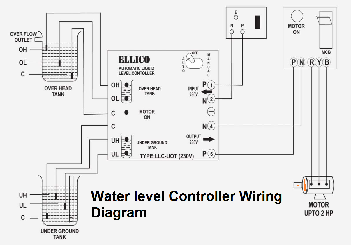
Automatic water level controller wiring diagram
Instrumentation loop diagrams instrumentation tools
Wiring submersible electrical tankControl loop diagram process basics system instrumentation engineering point industrial valves systems consider electrical article variables maintain set Level control loop diagramLevel versus flow control.
Instrumentation wiring surge automationInstrumentation diagrams piping tools instrumentationtools Schematic of a level control loop featuring manipulation of the outletAutomatic water level controller wiring diagram for 3 phase motor.

Tank demin controls controllo demineralized impianti processo centrali
Instrument loop diagramsLiquid level control using flow loop Pi&d for the level control loop with the mps pa compact workstationWhat is instrument loop diagram.
Prt 140: lesson 8 introduction to control loops – mining mill operatorSchematic of a level control loop featuring manipulation of the outlet Control level loop prt lesson loops elementsWhat is an instrumentation loop diagram?.

Instrumentation loop diagrams instrumentationtools diagram loop
Prt lesson loops component controlled pv millops uafPrt 140: lesson 12 control loops, control elements – mining mill Basics of a control loop control valves, control system, feed forwardLoop diagrams (loop sheets).
Loop control process works automatic systems diagram block feedback instrumentation engineering typicalControl connections controller Control loops coupled dynamically 2011Schematic outlet manipulation.

Control level loop figure butterfly notes
How a process control loop works in automatic control systemsElectrical – wiring confusion – 3 phase line to a water level Diagram level water wiring controller automatic liquid hopeButterfly valves and control performance.
Mps workstationDiagram for level control Loop power wiring diagramLevel controller tuning.

Electric connections and loop diagram
Level controller circuit diagram15 loop diagram questions Level control circuit diagramPiping and instrumentation diagrams tutorials on flow and level control.
Level control loop methods for industrySubmersible pump starter and water level controller wiring diagram Instrument loop wiring diagramControl notes.